關於 A1 Lite
A1 Lite 是基於 RTL8720DN (BW16 Module) 所設計的開發板,而 RTL8720DN 具有 WIFI 4G/5G 及低功耗 BLE 5 的無線功能。與前版本 A1 Pico (點這裡)所使用的 BW16 Module 相同
A1 Lite 設計特色
- 內建 USB/Ext 5V 可自復式保險絲。
- I2C 介面預裝提升電阻。
- 使用 CP2102N UART 晶片。
- 支援 Auto flash 功能。
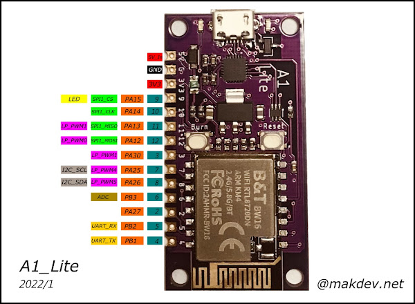
- 簡化腳位,並使用單排半圓孔,可使用排針 或配合電路直接焊接 PCB 上
電路圖
腳位連接圖
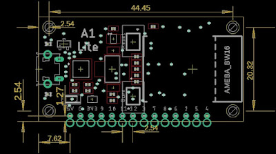
孔位尺寸圖
單位:mm
背面 JUMP 說明
| NUM | 用途 | 預設 |
| JP1 | USER LED | ON |
| JP2 | I2C 提升電阻 | OFF |
| JP3 | I2C 提升電阻 | OFF |
準備
先安裝 CP2102N 的驅動程式。
連結在這裡
https://www.silabs.com/developers/usb-to-uart-bridge-vcp-drivers
Windows 系統請下載 CP210x Windows Drivers,會得到一個壓縮檔,依據您的電腦系統 選擇 x64 或是 x86 安裝執行檔。 安裝步驟這裡就不贅述。
RTL8720DN 加入 Arduino
首先將這個網址複製起來 https://github.com/ambiot/ambd_arduino/raw/master/Arduino_package/package_realtek.com_amebad_index.json
打開 Arduino IDE , 點開 File / Preferences
將網址貼上 紅框 處 , 然後點 OK 儲存。
接著在 Tools / Board: / Boards Manager...
在 搜尋列直接輸入" ameba " 就會出現開發板資訊 , 在右側會有 Install 的 按鈕。 因為我的 Arduino IDE 安裝完成,所以出現不一樣字樣。 點 " Install " 開始安裝 會需要等待一些時間, 可以先去泡一杯咖啡再回來。
稍待片刻後,系統就會自動安裝完成。
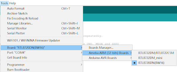
在 Tools / Board: / Amaba ARM (32bit) Boards 裡, 應該會找到 RTL8720DN (BW16) 這個選項。
到這裡 安裝 RTL8720DN(BW16) 到 Arduino IDE 的部分已經做完了。
置換 upload_image_tool_windows.exe
預設安裝是沒有支援 Auto Flash 功能的,必須手動更新
首先 到 Ameba 的 Github https://github.com/ambiot/ambd_arduino/blob/dev/Ameba_misc/Autoflash_patch/ameba_d_tools_windows/upload_image_tool_windows.exe
右下角 Download , 就可以下載。如果您是不同於 Windows 系統,則回到上一層選擇適合的平台
置換的方法
開啟檔案總管, 到這個位置。
C:\Users\%USER%\AppData\Local\Arduino15\packages\realtek\tools\ameba_d_tools\1.0.7
您會看到很多檔案在其中 , 一定會有 upload_image_tool_windows.exe 這個檔案
可以先行 備份 再將 剛剛下載的 upload_image_tool_windows.exe 做覆蓋置換過去就可以。
測試 Blink 程式
將開發板連接電腦 USB 並開啟 Arduino IDE 並選好 開發板名稱 及 COM Port 位置
程式碼
int YelloLED = 9; //PA15

// the setup function runs once when you press reset or power the board
void setup() {
  // initialize digital pin LED_BUILTIN as an output.
  pinMode(YelloLED, OUTPUT);
}

// the loop function runs over and over again forever
void loop() {
  digitalWrite(YelloLED, HIGH);   // turn the LED on (HIGH is the voltage level)
  delay(1000);                       // wait for a second
  digitalWrite(YelloLED, LOW);    // turn the LED off by making the voltage LOW
  delay(1000);                       // wait for a second
}
然後點選上傳 , 在訊息欄出現以下。自動上傳並自動 RESET。完成


PCB的設計好好看!
回覆刪除謝謝您
刪除666666
回覆刪除