2024年3月15日星期五

[AMEBA] Datalogger Iot (RTL8720DF) Arduino/RS485應用板

Datalogger IOT(RTL8720DF) Arduino/RS485應用板 有以下特點

  1. 針對工業應用需求設計的 UNO 開發板
  2. 內建 qwiic 介面,支援多種 I2C 傳感器模組快速擴充
  3. 集成 RS485 通訊介面,內置 PTS 和 TVS 保護電路
  4. 內置專用 PMS5003 顆粒物傳感器連接器,方便接線
  5. 支援 12V~24V 直流電源輸入,適用於工業電源供應
  6. PCB 板上設有電源管理、過載和短路保護功能
  7. 擴展接腳包括 GPIO、ADC、PWM 等,滿足多樣化需求
  8. 附帶 Arduino IDE 開發環境和豐富的範例程式碼
  9. 體積小巧,適合嵌入式工業設備和現場監控應用
  10. 可廣泛應用於工業自動化、環境監測、智慧城市等領域

Datalogger 應用板本體

  • DC IN : 6V ~ 24V
  • DC OUT: 5V /1A
  • Arduino uno 定位孔
  • 連接器: qwiic ( I2C)、UART(JST2.0)、RS485
  • UART 擴展
  • RS485 具有 TVS + PTS 保護

開發板針對工業應用的特點:

  1. 支持工業標準的 RS485 通訊介面及其相關保護電路
  2. 可接入常用的 PMS5003 顆粒物傳感器進行環境監測
  3. 適用於工業電源環境的 12V~24V 直流輸入設計
  4. 具備完整的電源管理和保護機制,提高系統穩定性
  5. 擴展接腳涵蓋工業控制所需的各類輸入輸出

核心

RTL8720DF
32-bit KM4 (Arm Cortex-M33 compatible)
32-bit KM0 (Arm Cortex-M23 compatible)
512KB SRAM + 4MB Flash

KEY FEATURES

Integrated WiFi 4 (802.11b/g/n 1x1) SoC
Dual-band, 2.4Ghz or 5GHzBluetooth LE 5.0
Bluetooth high-power mode up 10dB
Low Power Mode
Auto Download Mode
3 UART interface
1 I2C interface
2 SPI interface
12 PWM interface
1 IR interface
Max 18 GPIO

專用 USB 程式碼上傳工具


基本擴展板

擴展板由以下功能組成

  • OLED 0.96" 顯示器
  • 24C02 EEPROM x 1
  • SD CARD (Micro SD)
  • 2 個按鍵 ( Reset重置 及 USER Key)
  • 2.54mm 及 2.00mm 洞洞板自行功能擴展焊接區塊

資源

開發板介紹


安裝及使用


立即購買


2023年3月31日星期五

[Ameba] A1 PICO / RTL8720DN (BW16) and Arduino IDE (EN)

RTL8720DN

Realtek RTL8720DN is a wireless chip that supports both Wifi and Bluetooth, with Wifi supporting dual modes (802.11 a/b/g/n 1x1, 2.4GHz & 5GHz) and low-power BLE 5. The processor core is designed with dual processors, integrating ARM V8M Cortex-M33 (instruction set compatible with Cortex-M4F) and ARM V8M Cortex-M23 (compatible with Cortex-M0+). Wifi and BT share the same set of antennas, making hardware design simpler. The BW16 is a SOC module designed based on the RTL8720DN, which connects commonly used pins and uses a PCB antenna to make development easier.

Summary:
The core consists of KM4 Arm Cortex-M4 core @ 200 MHz and KM0 Arm Cortex-M0 core @ 20 MHz. WiFi supports 2.4G and 5G protocols, with a bandwidth range of 2.412-2.484GHz & 5.180-5.825GHz.

  • It supports HT20/HT40 modes
  • low-power mode
  • Bluetooth 5.0 LE
  • with a bandwidth range of 2.402GHz – 2.480GHz.
  • Operating modes include AP, Station, AP/Client. 
  • WiFi and BT share the same antenna.
  • 1 ADC
  • 2 UART interfaces
  • 1 I2C
  • 1 SPI
  • 4 PWM
  • and all pins can be used as GPIO.


To make it more convenient to use the RTL8720DN (BW16), I designed the A1 PICO development board.

Development highlights:

  • Built-in USB 5V self-recovery fuse.
  • Battery connection interface JST 2.00mm.It is not convenient to connect a fixed power source in many applications, so it will be more convenient in applications. If USB 5V is connected at the same time, it will automatically switch to USB as the main power source.
  • Because battery applications are required, I specially selected an LDO with good efficiency to maximize the battery's performance. The default voltage range is 3.6V ~ 4.2V.
  • Pre-installed I2C pull-up resistors.When used in I2C applications, pull-up resistors are always needed, and sometimes they cannot be found temporarily. Now, you only need to connect the short circuit pin.
  • Supporting Auto Flash function is also a major modification this time.


Connection diagram

RTL8720DN,BW16,ESP32


UART Driver

CH9102F
https://www.wch.cn/products/CH9102.html

Circuit diagram

RTL8720DN,BW16,ESP32


Arduino IDE

To get started, you need to install the Ameba board support package (BSP) for the Arduino IDE. Follow these steps:

  1. Open the Arduino IDE and click on File -> Preferences.
  2. In the Additional Boards Manager URLs field, enter the following URL:https://github.com/ambiot/ambd_arduino/raw/master/Arduino_package/package_realtek.com_amebad_index.json
  3. Click OK to save the changes.
  4. Next, open the Boards Manager by clicking on Tools -> Board -> Boards Manager.
  5. Search for "ameba" and select the "Realtek AmebaD Boards" package.
  6. Click on Install to install the BSP.
  7. After installation, select the "Ameba RTL8720DN / BW16" board from the Tools -> Board menu.

You are now ready to program the Ameba board using the Arduino IDE.
Please enable the Auto Upload mode as this development board has the Auto flash feature for automatic uploading.


Demo video

Resources


2023年3月29日星期三

[Ameba] RTL8720DN 搭配 TFT_eSPI 控制 ILI9341 顯示器 (Arduino/BW16)

RTL8720DN 與 TFT_eSPI

這期簡單介紹 RTL8720DN 使用 TFT_eSPI 控制 ILI9341 240 x 320 規格的顯示器,目標是顯示 240 x 320 的圖檔。 硬體部分是 A1 Pico 搭配 擴充板

設置 TFT_eSPI

首先, 先行安裝 TFT_eSPI Library ,我這裡安裝的是 V2.5 版本。

安裝完成後,打開 Arduino Library 的位置。如果不知道在哪裡,請在 File / Preferences 找到 Sketchbook location 欄位。這就是目前您的 Arduino Library 的位置。

並找到 TFT_eSPI 的 資料夾,我們要在這裡設定一些項目。

首先下載這個檔案
https://github.com/cold63/TFT_eSPI/blob/master/User_Setups/Setup302_BW16_ILI9341.h

下載完成後,複製到 TFT_eSPI/User_Setups 的位置。
接下來,在 TFT_eSPI 找到 User_Setup_Select.h 並使用 notepad 打開它編輯

找到這一行 ,並在前面給它加註解 //


//#include "User_Setup.h"


在這一系列的 User_Setups 內找出最後一行,並加入底下這一敘述
#include "User_Setups/Setup302_BW16_ILI9341.h"

以下這 3 pin ,就按照實際狀況調整。如果是 A1 Pico 的擴充板,就不需要更改。


#define TFT_CS    9  // Chip select control pin
#define TFT_DC    3  // Data Command control pin
#define TFT_RST   2  // Reset pin (could connect to RST pin)

製作圖片

我們的目標是 240 x 320 pix 的顯示,而且想輸出滿版的畫面。所以,先將圖片製作好。我的圖片是

然後到這個網站
http://www.rinkydinkelectronics.com/t_imageconverter565.php

在 Picture to convert 選擇剛剛製作好的圖片,並上傳。
上傳完畢,再點 Make File 按鈕。便會要求下載 *.C 的 檔案。

開啟 Arduino IDE 並建立 新的Sketch。
在 Arduino IDE 最右邊,有個 點點點

它會要 輸入 file name
我這裡是取名為 sample.h ,或是其他的名字的 *.h
並將剛剛下載的 *.c 打開並全部複製到 sample.h 裡

以下是主程式內容


#include "TFT_eSPI.h"
#include "SPI.h"
#include "sample.h"

TFT_eSPI tft = TFT_eSPI();

void setup() {
  // put your setup code here, to run once:
  tft.init();
  tft.setRotation(1);  // landscape

  tft.fillScreen(TFT_BLACK);

  // Swap the colour byte order when rendering
  tft.setSwapBytes(true);

  // Draw the icons
  tft.pushImage(0, 0, 320, 240, sample);


}

void loop() {
  // put your main code here, to run repeatedly:

}

編譯好並上傳。
以下是呈現的結果。

Github 原始碼

https://github.com/cold63/Arduino_Code/tree/main/ShowLogo_240_320

相關連結

A1 Pico / RTL8720DN
https://www.makdev.net/2021/09/ameba-ameba-bw16-arduino-ide.html

RTL8720DN 二合一擴充板
https://www.makdev.net/2022/09/ameba-bw16-type-c-shield.html

影片展示


2023年3月24日星期五

[Ameba] RTL8720DN 與 溫溼度感測 DHT20 實作 (Arduino/BW16)

實作要點

本次實作使用 RTL8720DN 透過 I2C 介面讀取 DHT20 溫溼度感測及在透過 I2C 介面將讀取結果顯示於 OLED SSD1306。

硬體清單

軟體實作

軟體主題有 2 個項目,
OLED SSD1306 及 DHT20.OLED SSD1306 使用 u8g2 程式庫。 DHT20 的程式庫則使用 DFRobot 的 DHT20 程式庫 https://github.com/DFRobot/DFRobot_DHT20 )

u8g2 library 先在 Arduino IDE 裝好 u8g2 程式庫


DHT20 程式庫

準備就緒後,進行程式段。


void setup(){
  Serial.begin(115200);
 
  //Initialize sensor
  while(dht20.begin()){
    Serial.println("Initialize sensor failed");
    delay(1000);
  }
  
  u8g2.begin();
  u8g2.setFont(u8g2_font_8x13_mf);
  u8g2.setFontPosTop();
  fontHigh = u8g2.getMaxCharHeight();
  fontWidth = u8g2.getMaxCharWidth();
  
  u8g2.clear();
  u8g2.setCursor(0,0);
  u8g2.print("temp:");
  u8g2.updateDisplay();
  delay(100);
  u8g2.setCursor(0,fontHigh);
  u8g2.print("Humidity:");
  u8g2.updateDisplay();
}

void loop(){
  //Get ambient temperature
  tempValue = dht20.getTemperature();
  Serial.print("temp:"); Serial.print(tempValue);Serial.print("C");
  delay(100);
  
  //clean temp display
  u8g2.setCursor(fontWidth * 5 + 1,0);
  u8g2.print("    ");
  u8g2.updateDisplay();
  //display temp value to oled
  delay(10);
  String tempStr = String(tempValue,2);
  u8g2.setCursor(fontWidth * 5 + 1,0);
  u8g2.print(tempStr + "C");
  u8g2.updateDisplay();
  delay(500);
 
  //Get relative humidity
  humidityValue = dht20.getHumidity()*100;
  Serial.print("  humidity:"); Serial.print(humidityValue);Serial.println(" %RH");
  delay(100);
  
  //clean temp display
  u8g2.setCursor(fontWidth * 9 + 1,fontHigh);
  u8g2.print("    ");
  u8g2.updateDisplay();
  
  //display temp value to oled
  delay(10);
  String humidityStr = String(humidityValue,2);
  u8g2.setCursor(fontWidth * 9 + 1,fontHigh);
  u8g2.print(humidityStr + "%");
  u8g2.updateDisplay();
  delay(1000);
}
RTL8720DN,BW16

Github 原始碼

https://github.com/cold63/Arduino_Code/tree/main/Ameba_DHT20

相關連結

A1 Pico / RTL8720DN
https://www.makdev.net/2021/09/ameba-ameba-bw16-arduino-ide.html

RTL8720DN 擴展板
https://www.makdev.net/2022/09/ameba-bw16-type-c-shield.html

2023年1月4日星期三

[Ameba] RTL8720DN 與 V7RC App 藍芽控制

Ameba 與手機連結

V7RC 是由 嵐奕科技 所開發的 App , 可以在 iOS 及 Android 系統運行。 V7RC App 可透過 藍芽及 WiFi 控制一般遙控車或是遠端控制應用。 在這裡做簡單直覺的範例做為基礎,望在爾後做更多的應用。

首先,開啟 範例
File / Examples / AmebaBLE / BLEUartService

ESP32,RTL8720DN,BW16

直接編譯並上傳至 RTL8720DN

V7RC App

設定連接藍芽

ESP32,RTL8720DN,BW16,V7RC

選定 車輛模式

ESP32,RTL8720DN,BW16,V7RC

開啟 Arduino IDE 的 Serial Monitor

移動 左右舵 及 上下舵
節錄一小段反饋

Received string: SRV1500150015001500#

SRV1500150015001500# 是由 V7RC 反饋的訊息

所以是
SRV (前綴碼) + 4 組 4 位數 + '#' 結束符
所組成的
前綴碼會依不同模式,而有所不同.
例如:
車輛: SRV
坦克: SRT

只要針對反饋的數值做處理就可以對我們的標的做控制。
到這裡,可以操作 左右舵及上下舵 看看有甚麼變化,這裡就不贅述

建立結構


typedef struct{
    bool reciveCMDFlag;
    int  ReciveValue;
    int  Pin;
    AmebaServo Servo;

}_rCMD;

uint8_t DefinePin[2] = {3,12};

定義 3,12 為PWM 輸出腳位

建立 - 解析反饋訊息


void ParseCMDString(String cmd)
{
    int comdLength = cmd.length();
    if(cmd.charAt(comdLength - 1) != '#')
        return;
    if(cmd.indexOf("SRV") > -1 ){
        int x = 3;
        int ValueIndex = 0;
        while(x < comdLength - 1){
            if(x + 3 < comdLength){
                String _NumString = cmd.substring(x,x + 4);
                
                if(ValueIndex < MaxNumValue){
                    if(bleReciveData[ValueIndex].ReciveValue != _NumString.toInt()){
                        bleReciveData[ValueIndex].ReciveValue = _NumString.toInt();
                        bleReciveData[ValueIndex].reciveCMDFlag = true;
                    }
                }
            }
            ValueIndex++;
            x += 4;
            Serial.println();
        }
        
    }
}

這個解析函式,將放在 writeCB call back function 裡
會自動填入 bleReciveDate 這個 Arrary.

當 reciveCMDFlag 為 true , 在 loop()裡就會個別對 sg90 Servo 控制。


void loop()
{

    while(Count < MaxNumValue) {
        
            if(bleReciveData[Count].reciveCMDFlag && bleReciveData[Count].Pin == 3){
                bleReciveData[Count].reciveCMDFlag = false;

                int Angle = map(bleReciveData[Count].ReciveValue,1000,2000,0,180);
                bleReciveData[Count].Servo.write(Angle);
            }
            

            if(bleReciveData[Count].reciveCMDFlag && bleReciveData[Count].Pin == 12){
                bleReciveData[Count].reciveCMDFlag = false;

                int Angle = map(bleReciveData[Count].ReciveValue,1000,2000,0,180);
                bleReciveData[Count].Servo.write(Angle);

            }

        
        Count++;
    }
    Count = 0;
    delay(1);
}


另外,在原範例的


Rx.setWriteProperty(true);

改為


Rx.setWriteNRProperty(true);

這個範例是控制 2個 SG90 Servo,若控制不同裝置時,例如: 驅動馬達,就要視情況再修改程式


原始程式碼

https://github.com/cold63/Arduino_Code/tree/main/V7RC_RTL8720DN


相關連結

iOS V7RC App
https://apps.apple.com/tw/app/v7rc/id1390983964
Android V7RC App
https://play.google.com/store/apps/details?id=com.v7idea.v7rcliteandroidsdkversion&hl=zh_TW&gl=US


[Ameba] RTL8720DN GPIO 中斷

使用中斷

GPIO 中斷對於 MCU 來說是非常好用的功能,並可以幫助時序的問題。可以用來偵測輸入開關,或是遮斷器的應用,抑或是用來偵測時脈的 Timing。 Ameba 的GPIO 中斷使用方法有稍微的不同,我們用簡單的範例來玩玩看。

觸發點

標準的時脈 (或是另一個說法 -> 方波) ,有上升段 (RISE) 及 下升段 (FALL)。 在 Setup() 就需要指定觸發點在何處,這會和您的電路有關。以這次的範例是以 RTL8720DN 擴展為例,User key 指定 IO Pin 為 6 ,接入開關後接地。 所以觸發點為 下升段(FALL)

波形示意圖

ESP32,RTL8720DN


User Key Button 電路


範例說明

範例在 ”File” -> “Example” -> “AmebaGPIO” -> “LED_InterruptCtrl”
打開後先另存 Save as ...
針對 擴展板 修改,指定 IO 6 為 偵測腳,IO 9 為 A1 Pico 的 LED


int button = 6;
int led    = 9;

觸發點為 FALL -> INPUT_IRQ_FALL


pinMode(button, INPUT_IRQ_FALL);

用 digitalSetIrqHandler f指定反饋 function


digitalSetIrqHandler(button, button_handler);

void button_handler(uint32_t id, uint32_t event) {}

這個範例的結果是 按 User Key 並放開,LED 會亮。再按一次 LED 會滅。

範例程式碼

https://github.com/cold63/Arduino_Code/tree/main/Interrupt_Ctrl_LED


2022年12月23日星期五

[STM32] FreeRTOS 手動移植至 CubeIDE 過程記錄

FreeRTOS

FreeRTOS 是一種即時作業系統,非常適用於微控制器應用。當然 STM32 也是在其中最適合於 FreeRTOS 操作的微控制器,這次來介紹 CubeIDE 環境中如何手動加入 FreeRTOS 系統。這次使用的開發板是 NUCLEO-L476RG,IDE 是 CubeIDE。

下載 FreeRTOS

在 FreerRTOS (https://www.freertos.org/) 直接下載,目前是 FreeRTOSv202112.00 這個版本

STM32,FreeRTOS

建構 FreeRTOS

下載後,解開壓縮檔。有幾個資料夾及檔案 (FreeRTOS,FreeRTOS-Plus,tools .....etc),我們只要 " FreeRTOS " 這個資料夾及內容。我採取的是刪除法,先建立一個空的資料夾,然後將 FreeRTOS 複製到剛建立的資料夾內。

複製完成後,直接在這個臨時資料夾內操作。

FreeRTOS 資料夾內有 Demo , License , Source , Test 等等內容。保留 License , Source,其他都刪除。

直接到 Source\portable 內 ,保留 GCC , 及 MemMang 這兩個資料夾,其他刪除。

L476RG 是個 M4 及含 FPU 運算的微控制器,所以

在 Source\portable\GCC 內, 只保留 ARM_CM4F 資料夾。

回到 MemMang 內
保留 heap_4.c , 其餘刪除

到這裡我們需要的檔案已經完成了。

CubeIDE 開啟新專案

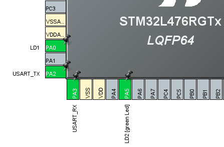
我們設定 2 個 GPIO-OUT , 分別是 LD1 & LD2

STM32,FreeRTOS

在 NVIC 中斷設定, 優先權設為 NVIC_PriorityGroup_4

STM32,FreeRTOS

接著產生 BSP code。

調整

產生 BSP code 後,開始做相對應的設定。
複製 FreeRTOS code。

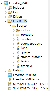
在 "建構 FreeRTOS" 所以建立的資料夾, 直接用拖拉的方式。複製到 CubeIDE 左側的 Project Exploper。

STM32,FreeRTOS

開啟 Project / Properties 對話框

找 C/C++ General / Paths and Symbols , 分別在 Includes , Source Location 這兩個標籤 (Tab) 設定

Includes :

FreeRTOS/Source/include
FreeRTOS/Source/portable/GCC/ARM_CM4F

STM32,FreeRTOS

Source Location :

加入 FreeRTOS/Source

STM32,FreeRTOS

修改 stm32l4xx_it.c


void SysTick_Handler(void)
void PendSV_Handler(void)
void SVC_Handler(void)

3個 function 用 /**/ 注釋掉

建立 FreeRTOSConfig.h


在 FreeRTOS 中找到
FreeRTOS/Demo/CORTEX_M4F_STM32F407ZG-SK/ FreeRTOSConfig.h
複製到 專案資料夾的 Core/Inc 內


內容做小修改


#ifdef __ICCARM__
    #include 
    extern uint32_t SystemCoreClock;
#endif

改成符合 CubeIDE


#if defined(__ICCARM__) || defined(__CC_ARM) || defined(__GNUC__)
    #include 
    extern uint32_t SystemCoreClock;
#endif

以下 2 個參數改為 0


#define configUSE_IDLE_HOOK                0
#define configUSE_TICK_HOOK                0

範例: 測試點亮 LED

到這裡, 開始寫 code
首先在 main() 前複製 這 2 個空 function


void vApplicationMallocFailedHook( void )
{
    /* vApplicationMallocFailedHook() will only be called if
    configUSE_MALLOC_FAILED_HOOK is set to 1 in FreeRTOSConfig.h.  It is a hook
    function that will get called if a call to pvPortMalloc() fails.
    pvPortMalloc() is called internally by the kernel whenever a task, queue,
    timer or semaphore is created.  It is also called by various parts of the
    demo application.  If heap_1.c or heap_2.c are used, then the size of the
    heap available to pvPortMalloc() is defined by configTOTAL_HEAP_SIZE in
    FreeRTOSConfig.h, and the xPortGetFreeHeapSize() API function can be used
    to query the size of free heap space that remains (although it does not
    provide information on how the remaining heap might be fragmented). */
    taskDISABLE_INTERRUPTS();


    for( ;; );
}


void vApplicationStackOverflowHook( TaskHandle_t pxTask, char *pcTaskName )
{
    /* This function will get called if a task overflows its stack.   If the
    parameters are corrupt then inspect pxCurrentTCB to find which was the
    offending task. */


    ( void ) pxTask;
    ( void ) pcTaskName;


    for( ;; );
}

我們有 2 個 LED , 所以分別用 2 個 Thread 控制


static void Blink1_Task(void *pvParameters)
{
TickType_t xlastFlashTime;
xlastFlashTime = xTaskGetTickCount();


while(1){
     vTaskDelayUntil(&xlastFlashTime,500);


     HAL_GPIO_TogglePin(GPIOA, LD1_Pin);


}


}


static void Blink2_Task(void *pvParameters)
{
TickType_t xlastFlashTime;
xlastFlashTime = xTaskGetTickCount();


while(1){
     vTaskDelayUntil(&xlastFlashTime,500);


     HAL_GPIO_TogglePin(GPIOA, LD2_Pin);


}


}

在 main()


  xTaskCreate(Blink1_Task,"Blink1",128,NULL,1,NULL);
  xTaskCreate(Blink2_Task,"Blink2",128,NULL,2,NULL);
  vTaskStartScheduler();

執行效果是這 2 個 LED 看起來會像是同時間點亮。


範例 Source code 放在 Github,
https://github.com/cold63/STM32_Code/tree/master/Freertos_M4F